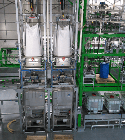

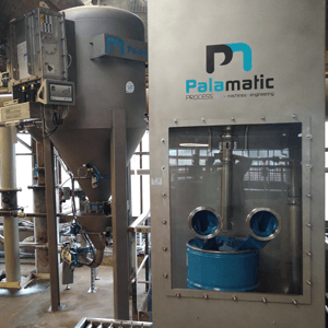

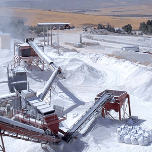


Transferring powders (dry raw materials) by pneumatic conveyance is a technology widely used in factories handling dry ingredients.
Pneumatic pressure conveying (low or high) offers many advantages due to the low number of mechanical parts in contact with your powders. It is the air velocity (pressure) which pushes the powder through the pipe ducts. A loss of transfer rate can appear when major changes occur!
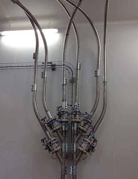
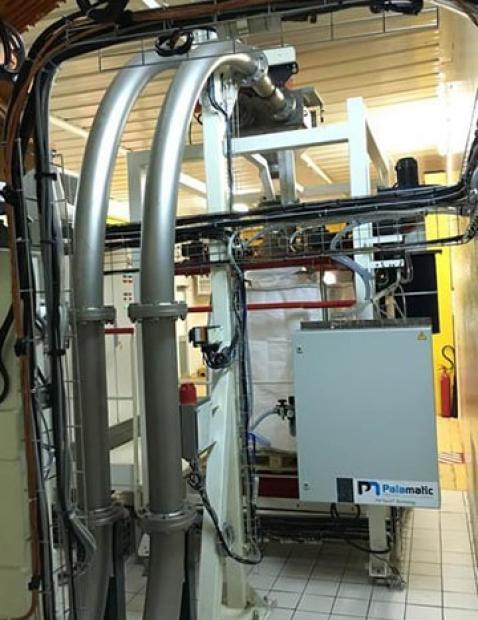
1. Pneumatic transfer piping
1- Piping diagram and design
During the study phase, the engineers will calculate the pressure drop generated by the geometry of the piping. Elbows, switches, vertical sections of piping all factor into pressure drops which is characterized by a "pressure loss". The longer the circuit with elevation and elbows, the greater the pressure required for the pneumatic conveying. This "no-load" pressure drop is then added to pressure produced for the introduction of the product.
In production, when modifying the pneumatic transfer circuit (modifying the piping), the pressure drop must be recalculated to ensure that the booster can still deliver sufficient transfer pressure. This usually happens when you want to add an additional end point such as a silo or a second mixing line.
For example, one additional pipe elbow equals a distance of 5 m of horizontal piping and one meter of vertical piping corresponds to a distance of 3 m of horizontal piping.
2- The conformity / connections of my piping
A faulty clamp / seal leads to an irreparable loss of power on your pneumatic transport. If you convey an abrasive powder, the risk of piercing the elbows or degrading your seals is real and proportional to the transfer speed of your powder (dense phase VS diluted phase)! Your transfer piping must be perfectly sealed.
When the pneumatic conveyor uses push transfer technology (dense phase transfer), the resulting dust emissions can be easily detected. On the contrary, when using vacuum pneumatic transfer (suction transfer), no dust is generated but flow loss is possible. Palamatic controllers integrate control cycles to ensure the sealing of the piping.
It is important to plan preventive maintenance on your elbow seals that are subject to water pressure as well as all sensitive mechanical elements like switches, filters and rotary locks.
2. Booster or vacuum pump
The driving force behind the air conveying system, the vacuum pump and booster, are the conveyor engine. It is the booster and vacuum pump that delivers the necessary pressure to push your powder over the desired distances. Regular maintenance of your pneumatic components is necessary to ensure the optimal operational condition of the turbines.
Valuable maintenance points are internal filters in booster and vacuum pumps, external filters where they exist, lubrication...
On vacuum pumps (vacuum transfer) using pallet technology, the condition of the pallets must be checked because successive stops and starts can cause additional wear and tear. Palamatic recommends the use of claw vacuum pumps which do not use vanes and therefore have better reliability.
Likewise, when you use vacuum handling, the vacuum pump is located at the end of the transfer line. Your vacuum pump is then exposed to the reliability of your separator cyclone. The quality of the cyclone filter is essential if you want to keep your powders out of the vacuum pump! Regular inspection of the cyclofilter is mandatory!
3. The rotary valve - starting point of the pneumatic transfer
In dilute phase pneumatic transfers, the introduction of the powder is handled by a rotary valve with side passage or a rotary valve with full passage. The rotary valve acts as a gateway by containing the pressure or depression present in the transfer piping. The pressure maintained by the lock is achieved by the adjustment between the rotating blades and the body of the lock. It is important to check the operating clearance between the blades and body. For handling abrasive powders, the use of reinforced locks or adjustable blades is strongly recommended.
As a general rule, a lock in good condition should generate less than 10% transfer air leakage. Check your degassing lines on the locks and ensure that the air flow generated is not excessive.

Need advice on your pneumatic transfer
equipment? I am at your disposal to help you.
Loïc, powder expert
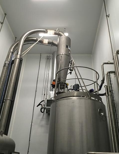
4. Cyclone separator, cyclofilter...the sore spot!
Your pneumatic transport in dense phase, in dilute phase, in pressure or depression necessarily includes a filter at the end of the line which provides the separation between your powders and the transfer air!
The condition of your filter is essential to ensure a good transfer operation. Regular automatic filter cleaning with the recommended pressure is essential. Palamatic pneumatic transfers incorporate pressure sensors (delta P) on the cyclofilters which provide pressure regulation, generated by the powder / air separation filter. The pre-defined pressure thresholds inform the automation of the need to unclog and / or change the filters. However, despite regular unclogging of the cyclofilter, a clogging in the heart of the filters can appear for several reasons (humidity, greasy products, sticky products, rate to high, etc.).
Conversely, an abrasive powder can cause the filters to break, causing dust to escape to your manufacturing workshop area. Too high of a velocity speed in the cyclone can lead to significant friction between the powders and the filter bags, resulting in accelerated deterioration.
Palamatic Process recommends that you install the pressure sensor directly on the cyclofilter to automate the control, or even periodic inspection if this sensor is local.
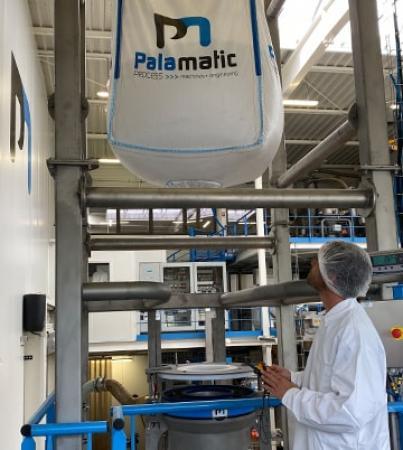
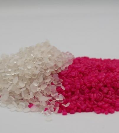
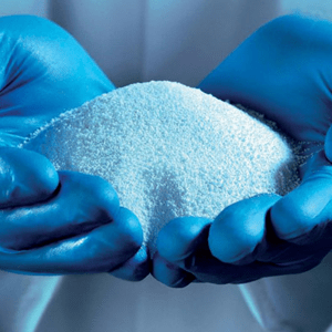
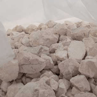
5. The transferred powder
Is your pneumatic transport installation in perfect condition but the material transfer is still performing poorly? Most likely, your powder is the cause of the drop in flow!
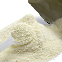
Powder variations like particle sizes, densities, fat content, temperature, etc., can factor directly into the impact of the capacities of your transfer system.
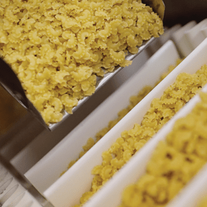
Pneumatic transfer applications should be set according to the powders being handled. Blockage of transfers, blockage of pipes or clogging of filters are typically due to the transferred materials.
The rotary valve or the transfer screw, which provides the metered feed of the powder into the pipes, must be controlled by a frequency converter in order to adjust the flow rate. The charge rate (product volume / air volume ratio) must be controlled by a pressure sensor. The more you introduce a large quantity of powder, or a powder with a high density, the higher the necessary transfer pressure must be. Therefore, a change of powder or a variation in flow rate on the rotary locks directly impact the transfer efficiency. For the technical definition of your pneumatic transfer, it is important to take into account the most restrictive powder in order to define the maximum pressure that the transfer pump must deliver.
The Palamatic Process Operations Department provides you with maintenance technicians with extensive experience in the fields of pneumatic transfers to assist you in your installation audits. Do not hesitate to contact us to optimize your pneumatic transfer lines.
See the whole range of pneumatic transfers, pneumatic transport, pneumatic conveyor, pneumatic handling PALAMATIC PROCESS.