
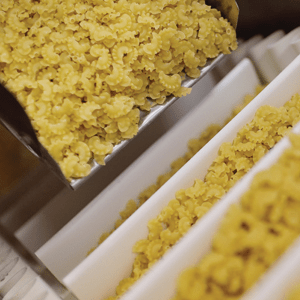


Processed product: Triuranium octoxide (U3O8)
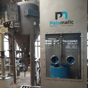
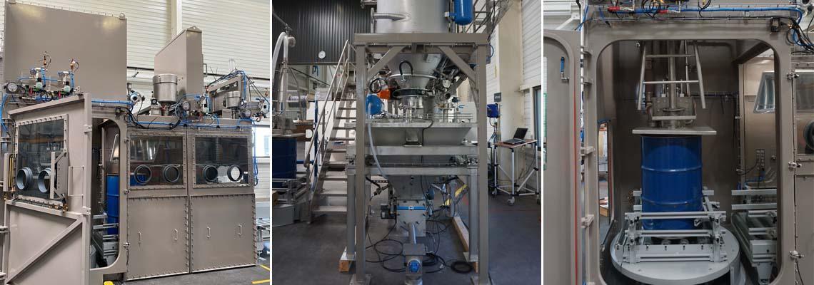
Drum Emptying Cabinet
Triuranium octoxide, also called triuranium octoxide or triuranium octoxide is a highly toxic product.
It is an odorless olive-green to black-colored bulk solid, which is a major component of yellow cake. Yellow cake represents an intermediate step in the process of manufacturing nuclear fuel from uranium ore.
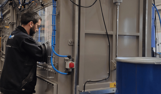
The installation concerns the supply of a production system that allows the emptying of drums, as well as the conveyance and dosing of the product in a confined enclosure.
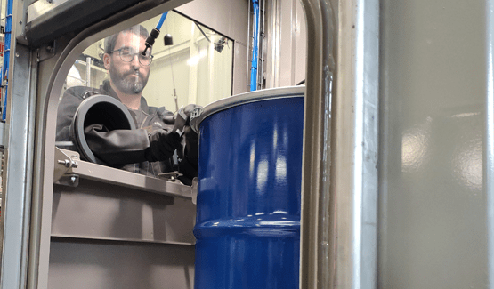
The drums treated are 380 kg fully-opened drums. The intervention of a single operator is necessary to ensure the proper functioning of the emptying station. The emptying time of a drum is approximately 45 min to 1 hour.
The whole assembly consists of 4 main zones corresponding to the 4 functions of the process:
1. Drum emptying enclosure made up of 3 airlocks and an unloading station via a suction pipe.
2. Complete integrated dust filter device connected to the enclosure.
3. Vacuum pneumatic conveying system connected to the suction cane.
4. Weight dosing system consisting of a buffer hopper and a screw feeder. The whole assembly is mounted on load cells.
ZONE 1 : DISCHARGE
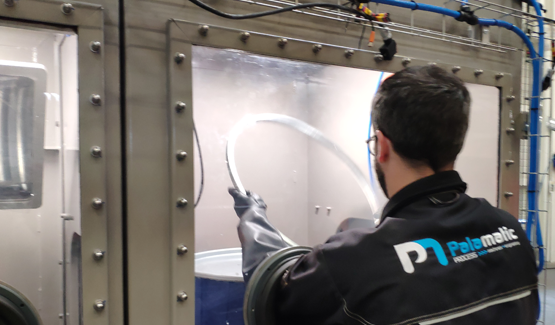
This enclosure guarantees optimum dust containment during the drum emptying operation. From the handling of the full containers to their evacuation once emptied, the cabinet is sized to allow the complete process sequence. A ventilation system is connected to the enclosure to provide a clean working atmosphere inside and outside the enclosure.
The enclosure is made up of 3 main airlocks:The full barrel is positioned on a motorized conveyor which starts outside the enclosure; the operation cycle can then begin.
Each airlock is separated by dust tight automatic guillotine doors.
This guarantees optimal containment and controlled aeraulic management at each stage of the emptying process.
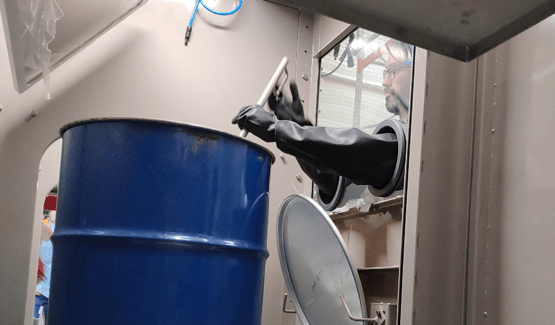
Airlock n°1: Clamp removal
Airlock n°1 consists of a glove box mounted on a glass window, a two-way motorized conveyor and a dust tight automatic guillotine door (drum entry).
This airlock is connected to the ventilation system, which allows the maintenance in depression of the latter and the constant renewal of the air. Once the drum has entered airlock n°1, the operator performs the following tasks:
• Loosening of lid clamp
• Clamp removal without removing the lid
Once this task has been completed, the operator presses the HMI to authorize the evacuation of the drum to airlock n°2.
Airlock n°2: Drainage and Control
Airlock n°2 is made up of 2 posts that are equipped with a glove box mounted on a glass window. This allows the operator to work in complete safety.
Station A consists of a two-way motorized conveyor, a dust tight automatic guillotine door, a cover support and a control mirror.
This position fulfills 3 functions:
- Removal of the lid
- Control of the barrel once emptied, using the mirror.
- Recapping the empty drum for evacuation.
Station B consists of the following elements:
- 1 two-way motorized conveyor, mounted on an automatic turntable
- 1 suction rod mounted on a descent and ascent mast
- 1 cover lid to confine the drum during the powder emptying phase
- 1 dust tight automatic guillotine door for the evacuation of the emptied drum to sas n°3.
The barrel, moving on the roller conveyor, is positioned on a turntable where it is immobilized.
A cover lid, which confines the open part of the drum during the emptying phase, is positioned on the head of the drum and helps guide the suction rod. The operator holds the suction rod which is mounted on a mast which can then start the emptying phase. The rod dips as the product is vacuumed out of the barrel.
The powder has poor flow properties so a rat-hole is created when the rod is lowered into the barrel. In order to allow the evacuation of the powder around this rat-hole, the operator activates the rotation of the drum using a foot pedal. The turntable makes quarter turns on demand.
Once the drum has been emptied, the operator authorizes its evacuation to the control station (Station A), using the HMI. The conveyor switches to "reverse" in order to evacuate the drum to the control station.
Once the check has been carried out at station A, the lid is repositioned on top of the barrel. If, however, the emptying of the drum was not satisfactory, a second vacuum cycle would be carried out at station B.
Once the drum has been completely emptied, the operator authorizes its evacuation from airlock n°2 using motorized conveyors and the guillotine door.
Airlock n°2 is also connected to the ventilation system to maintain and control the "cascade" of depression between the airlocks, which is necessary for the confinement and the renewal of the air. The drum is then evacuated to airlock n° 3 (control airlock). A non-contamination check is then carried out. This airlock can store a maximum of 4 empty drums for the re-clamping of the drum lid.
The drums are then moved to airlock n°4. This space is equipped with an opening for the entry and exit of personnel in order to manually evacuate empty drums, with their lids secured.
Airlock n°3: Final control and storage
Airlock n°3 collects the emptied barrels. A non-contamination check is then carried out. This airlock can store a maximum of 4 empty drums for the re-clamping of the drum lid.
This space is equipped with an opening for the entry and exit of personnel in order to manually evacuate empty drums, with their lids secured.
ZONE 2: VENTILATION
The containment enclosure is connected to a complete ventilation system. It allows the cabinet to be placed under negative pressure to maintain containment in the event of damage (pierced gloves, possible leaks, etc.) and the constant renewal of air in the airlocks.
This device consists of:
- 1 set of automatic management valves.
- 1 set of instruments (pressure sensor, pressure gauge, Delta-P, etc.)
- 2 cascading, high efficiency filtration units.
- 1 fan for depression.
The entire device is installed in the technical area.
ZONE 3: TRANSFER
This area is dedicated to the pneumatic vacuum transfer of the powder: a cyclo-filter, positioned on a support structure, is installed at the end of the pneumatic transfer piping. This cyclo-filter provides the air/material separation. The storage capacity of the cyclo-filter is 213 liters, i.e., the capacity of a drum. A primary filter is positioned upstream of the vacuum pump, which provides the depression necessary for the transfer of the material in the piping.
ZONE 4: DOSING
A dosing hopper (weighed dosing) is positioned under the cyclo-filter and mounted on a support structure equipped with load cells. It is connected to the cyclo-filter via a flexible fitting. A screw feeder is mounted at the outlet of the buffer hopper. The weighing of the hopper and the powder dosing mechanism allows continuous metering by weight.
A degassing filter positioned on the hopper balances the volumes. This filter can work both in pressure and vacuum applications.
The filter outlet is connected to the enclosure extraction circuit.
The dust is separated from the air flow by means of a filter element and falls back into the hopper due to the integrated compressed air cleaning system (reverse jet pulse technology). This feature functions as a means of reducing product loss to the filter.


